1
2
3
4
5
6
7
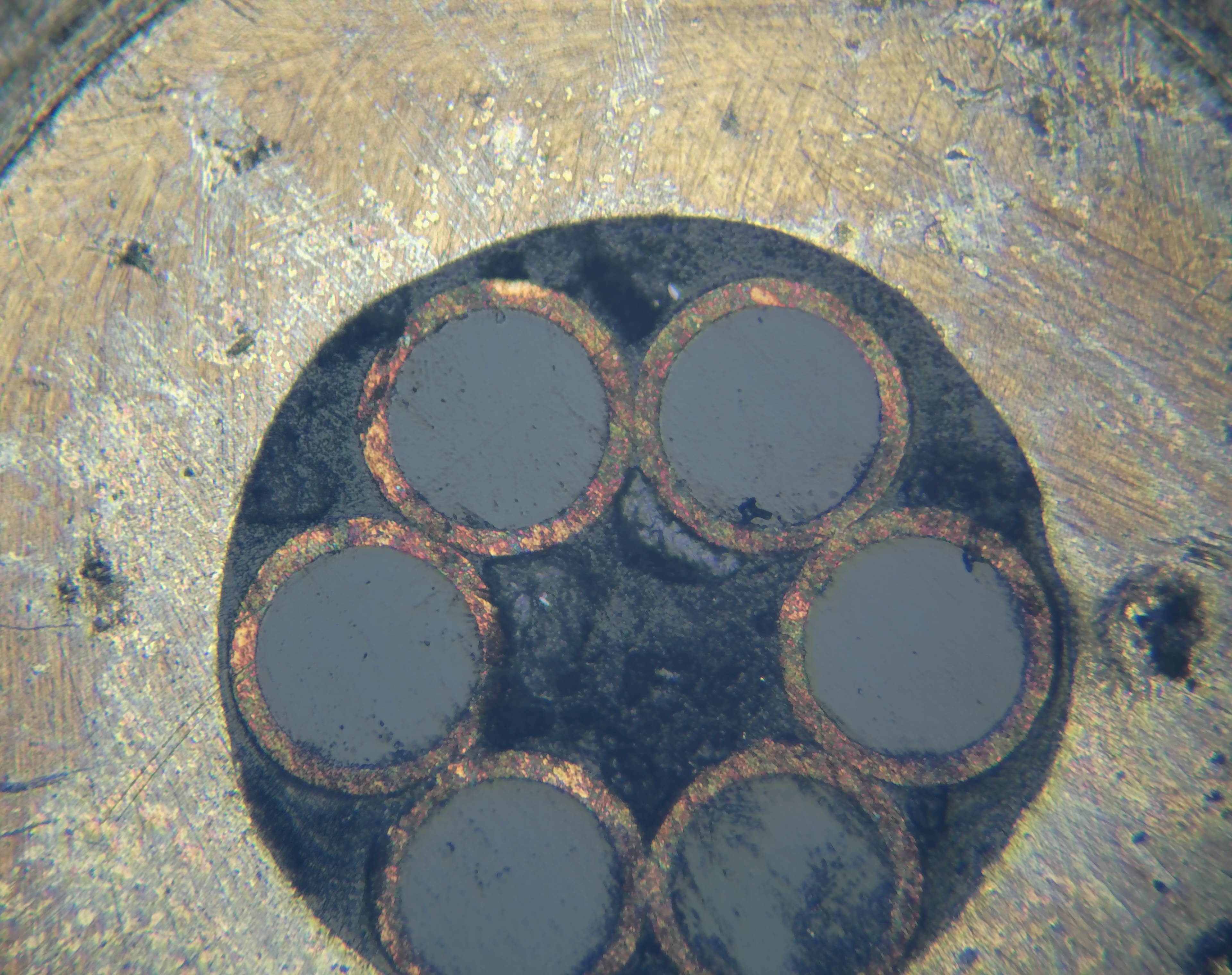
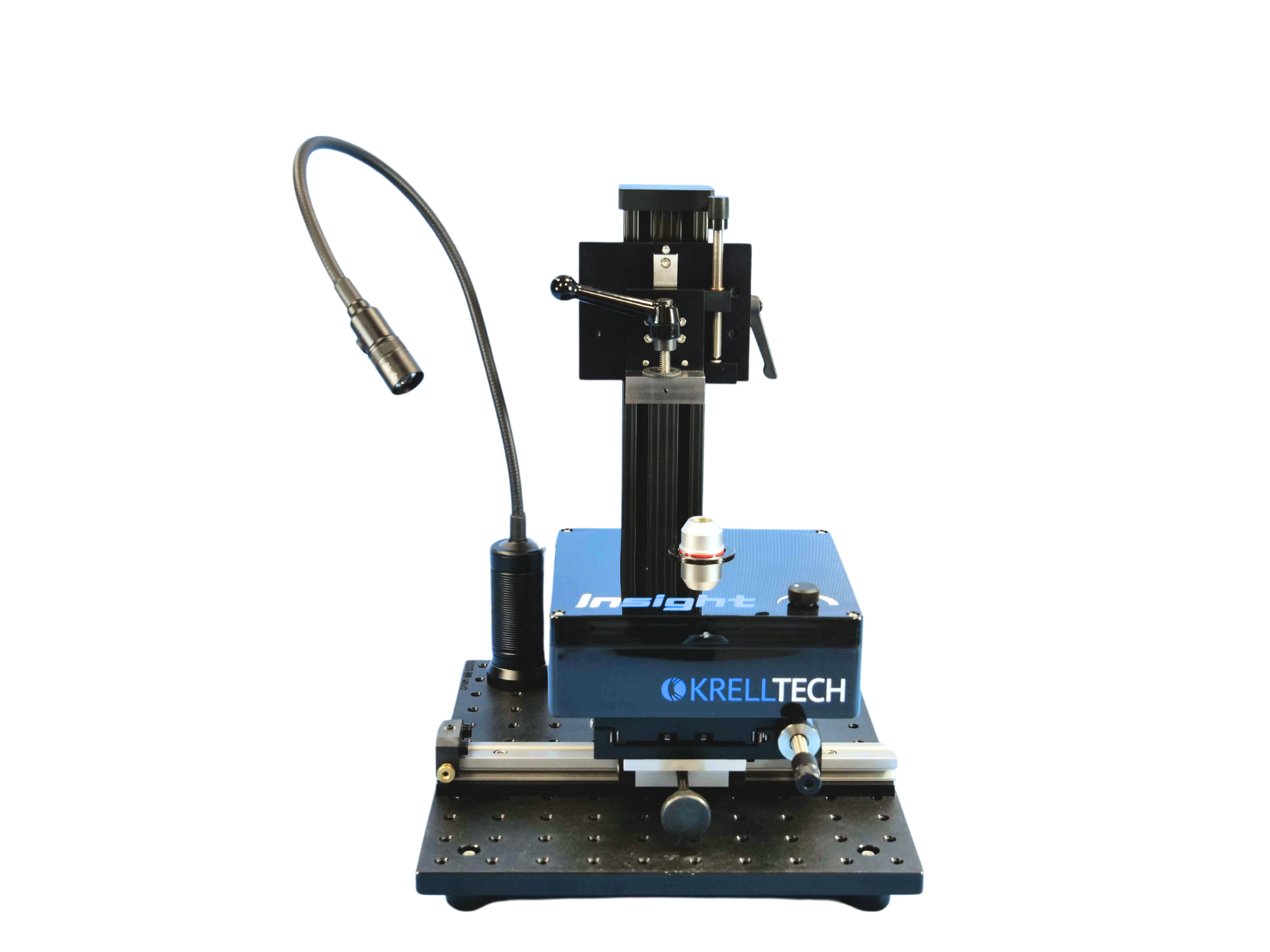
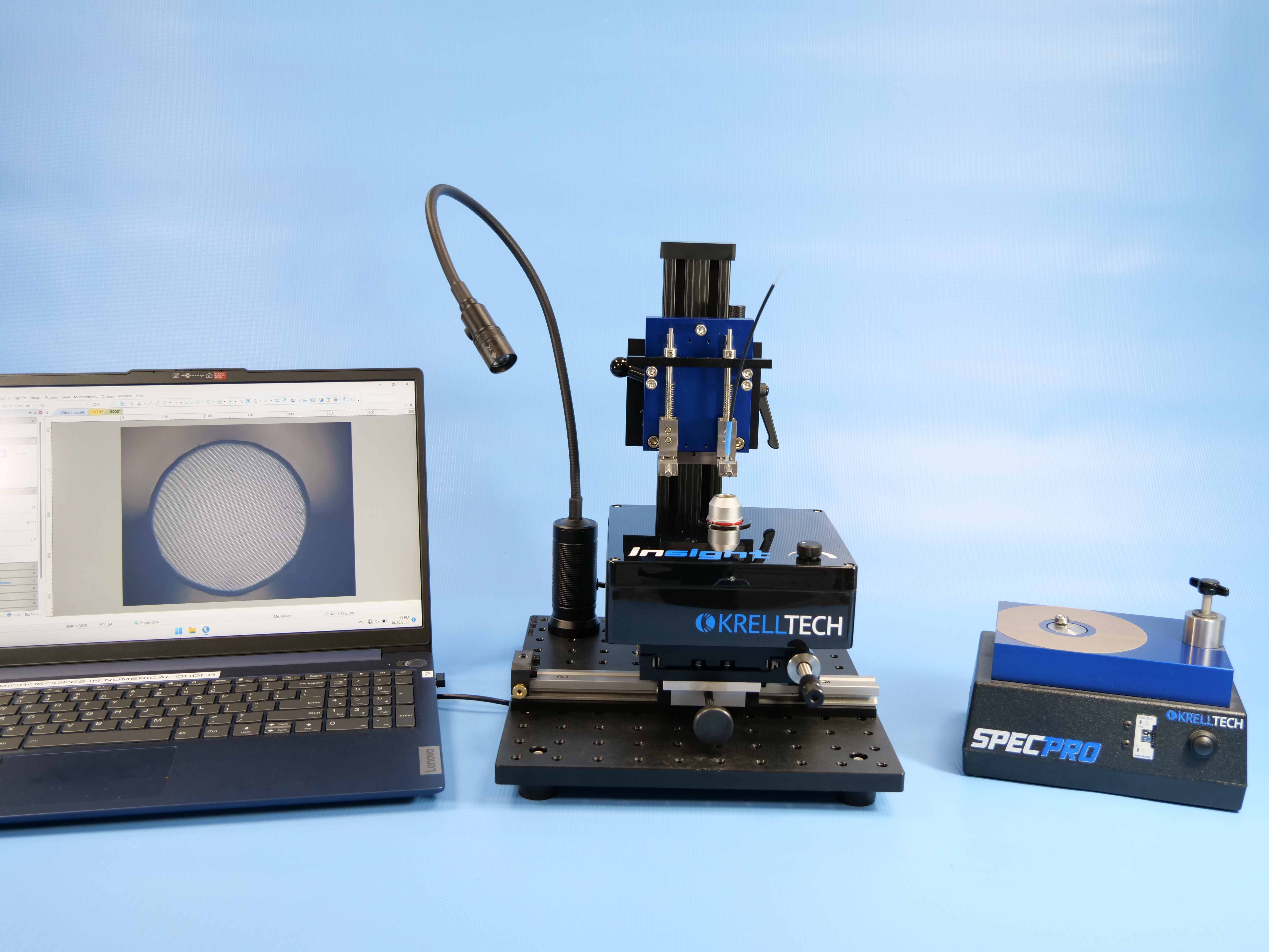
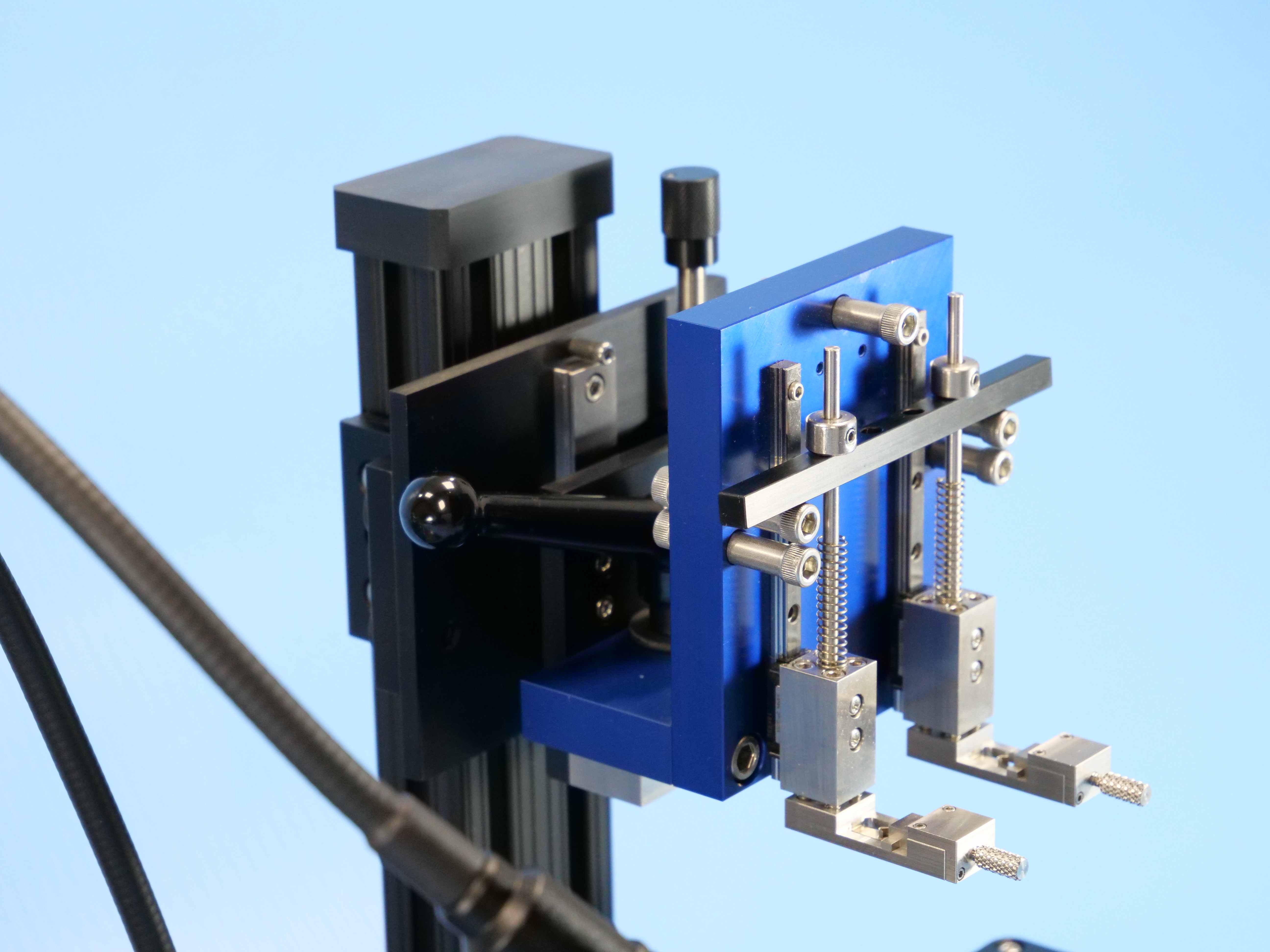
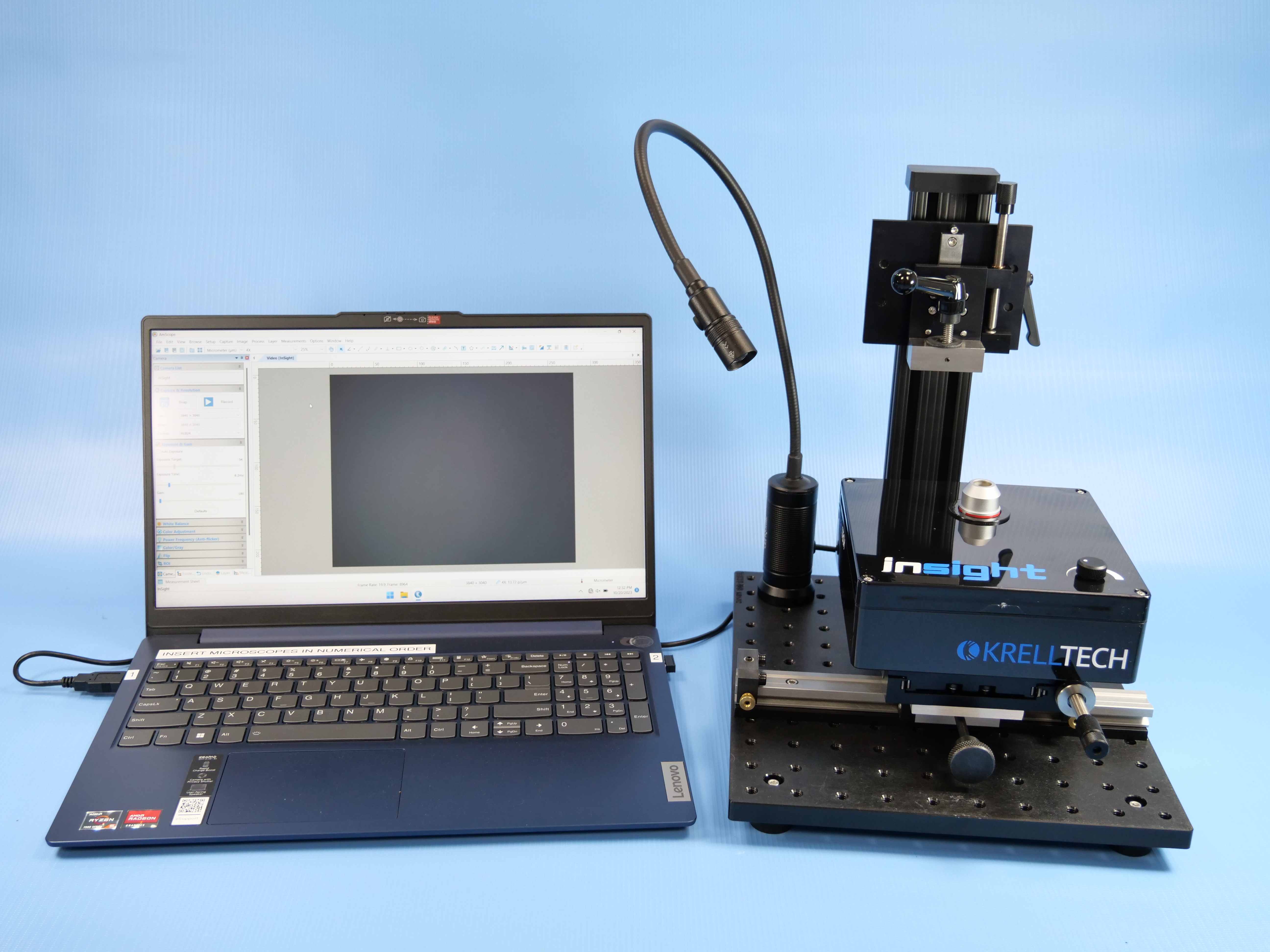
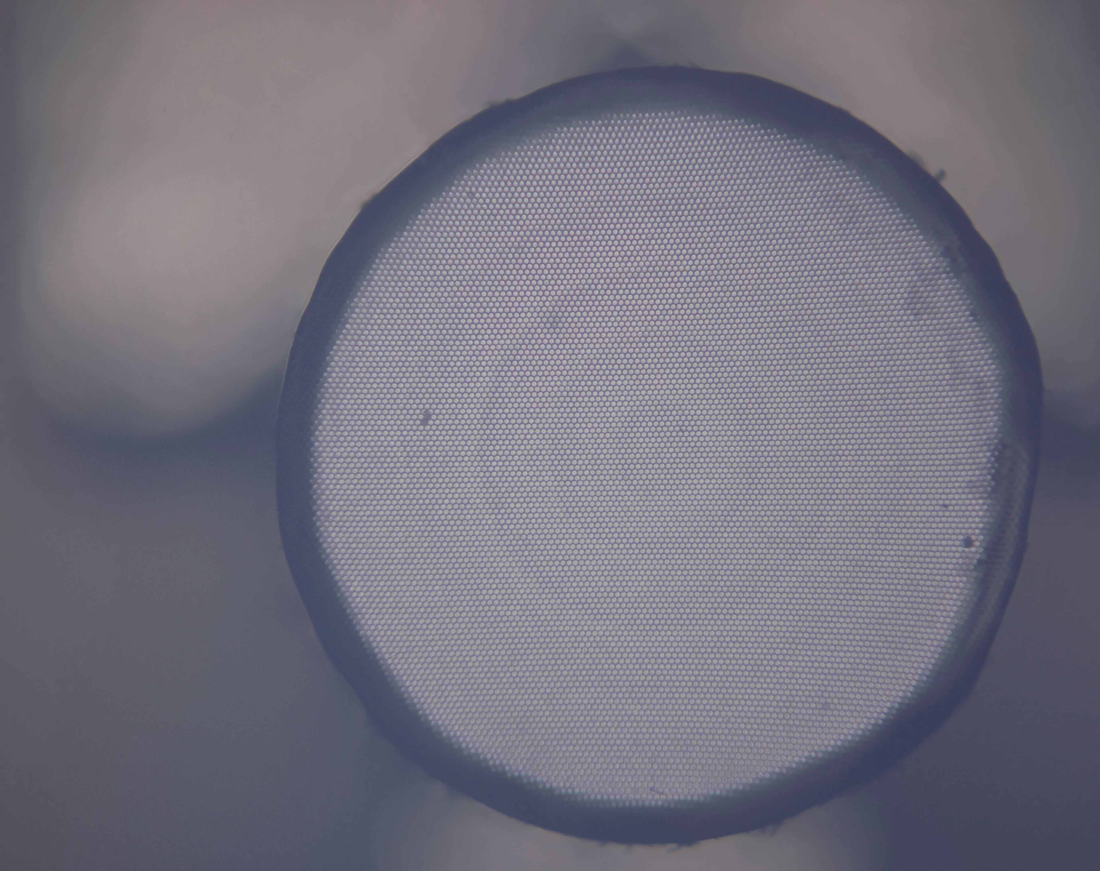
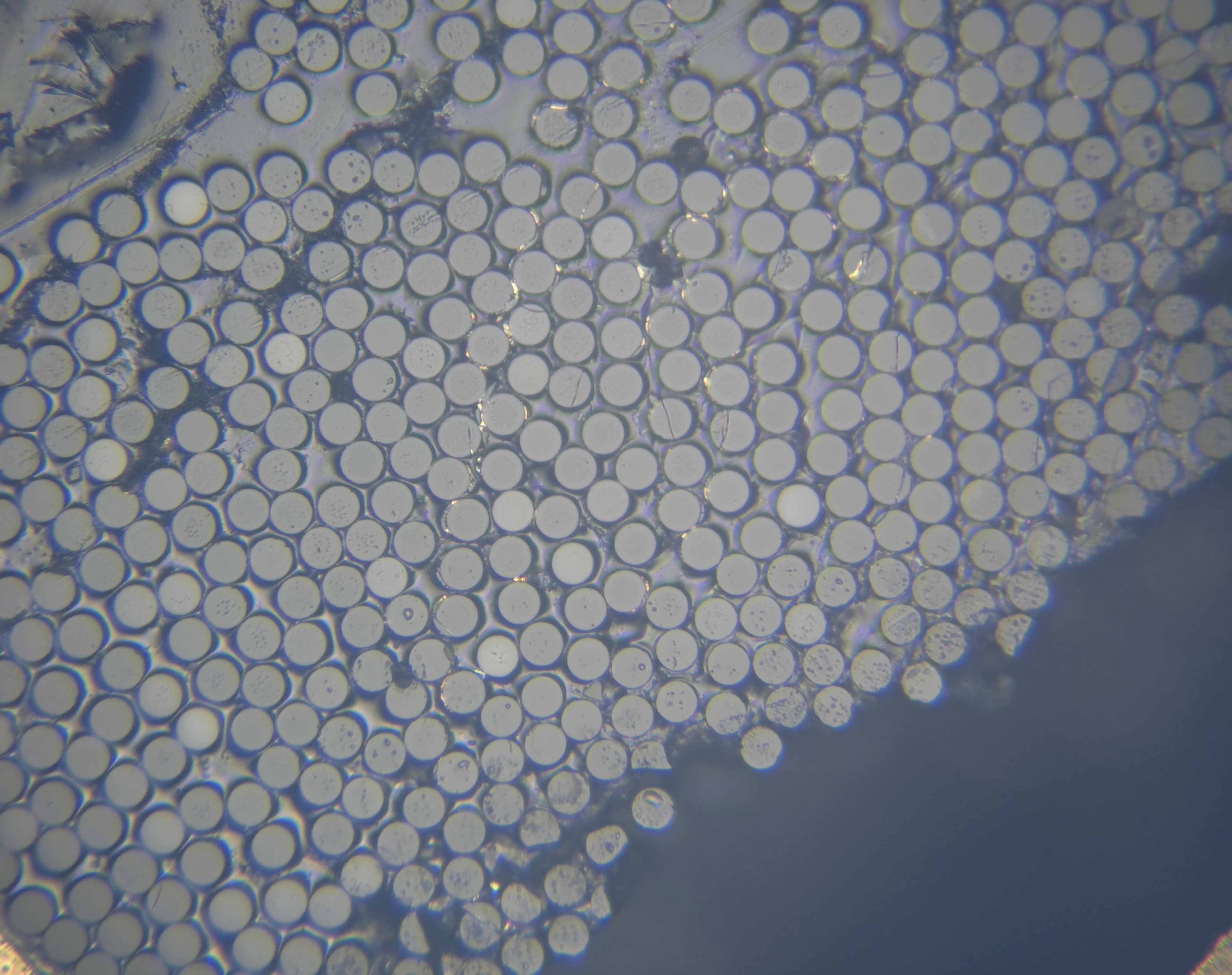
InSight™ In-line Video Inspection Station
InSight™ In-line Video Inspection Station is a dedicated video station for the inspection of fiber optic connectors and photonic components. All Krell polishing workholder fixtures can quickly engage with this system allowing in-line inspection without the need to remove the connector/termini/chip/component from the polishing fixture. This streamlines quality assurance and minimizes the change of component damage and contamination that can occur when removing and transfer parts back-and-forth between polisher and microscope. Magnification levels can easily be change by the simple exchange of optical objectives. InSight™ supports NOVA™, Scepter™, SpecPro™, FLex™, Radian™ and Proton polishing equipment and machines.